Friday, February 7, 2020

My Heathkit HW-101

I originally bought this Heathkit HW-101 back around 1993 from a friend at the Maysville NC hamfest. It had never been on the air, and my friend said they couldn't figure it out. It was originally built back around 1970, wouldn't work, and was put back in the box and stored away. After a little bit of work (assembly problems), it was on the air and playing like a new radio! I took it up to my Mom & Dad's lake house at Kerr Lake in NC, strung up some dipoles, and left it there...until January of 2020. I recently brought it home, and gave it a bit of a checkup, cleaning, and adjustment. It's on the air again, and just as good as it ever was.


Here's a little video after I finished up with a minor facelift on the rig. Receiving an SSB conversation on 40M at night. I have always loved these rigs, and have owned several over the years.


Here, I have the hood up. Tubes cleaned (they cool better when clean), sockets and all controls cleaned and lubricated, several mods done to improve the  SSB reception by increasing the BFO osc level and reducing the IF injection at the mixer. Also replaced a bunch of carbon resistors that had shifted values over the years.


I pulled the inner lower cover and cleaned the band switch. This one also has the CW filter.


Penta Labs 6146's in the PA! I neutralized them using the cold cathode method. I also gave the rig a full alignment and made a mod to improve the carrier injection null.


Cases and face plate cleaned, and looking great for a 50 year old rig!!


Ready to move her over to an operating position in Studio B!


Wired to a non-amplified D-104 mic, the transmit audio sound great and gets good reports. 


A little action on 40m SSB


Dave WB4IUY

Thursday, February 6, 2020

Wiring the shack...

I've had visitors and webcam folks ask: "What are you reaching under the table top to do?". This was always funny to me for some reason, so I decided to make a post and explain it, as well as my AC/DC power system. First, here's a basic pic of Studio A, my primary operating position. The 8' long main table was built for me back around 1993 by a good friend.


I have various radio gear scattered on 3 tiers of table and shelving. Almost all of it runs on low voltage DC. I have a large, deep cycle battery system in the garage (just on the other side of the RH wall in the photo). Those are charged by a pair of high current DC supplies, and diode switched to provide instant battery backup in case the AC mains are lost. I live in a rural area, and have a whole house generator to keep things powered, and opted to go this route to keep the bulk of the load off of the generator should I be on emergency power. The shack will run a few days like this, with no AC assistance from the generator, if needed. The shack computers are powered through some fairly large battery backup (UPS) systems to keep them online while the AC supply is cutting over from AC mains to the generator.


 On the top shelf, just to the right of the lamp, you'll notice a 5 position rotary coax switch mounted to the forward facing edge. This is how I select various HF rigs and a cable that runs out to Studio B, to the various antennas that are brought into the shack. It's an easy reach from my rolling chair :-)


In the pics above, you'll see the AC surge suppressors / power strips I use to power the various AC widgets and computer backups. I have those mounted along the inner rear edge of the table. Notice the copper pipe running lengthwise along the rear underside of the table? That is attached to a 6' copper ground rod, driven into the ground directly under that table. Radios, coax, and other items are all ground through that.


 From the DC supply system in the garage, I bring in a short run of 2/0 automotive battery cable, to a DC power distribution terminal block pair located in the center web of the underside of the table. From there, I connect all of the various DC radios and other devices through fuse blocks. This makes the addition of radios and such pretty easy. Again, you can see the ground bar running along the bottom of the table.


Now, on to "what I'm reaching for under the table". Along the front inner edge of the table, I have 3 antenna switches mounted. I easily reach under the front edge of the table, and select the HF yagi, dipoles, slopers, VHF yagi, 6m yagi, Cantenna dummy load, etc. That keeps my shelving and desk top free of antenna switches and a bunch of bulky cables that's always trying to pull them off the table.

This is pretty basic stuff, and I'm sure there's much better ways to do it, but it's how I do it. Hope that helps someone with their shack layout!

Dave WB4IUY


Tuesday, February 4, 2020

Straight Key Century Club

Wow, so glad I found this group. Years ago, I really enjoyed using my straight keys. Over time, I started using my Iambic paddles and electronic keyer for contecting and such, and the keyboard for CW rag chews. I totally forgot how much fun the old keys were. I found this group, dusted off one of my old keys, and jumped in. Lots of fun...my fish isn't what it once was, but it's getting better. Check them out on facebook and on their website at www.SKCCGroup.com 

Dave WB4IUY
www.WB4IUY.net


Resurrection of an Alinco DR-112

I received an Alinco DR-112 2 meter rig from a friend that needed repair. Someone had tested it and told him it needed a crystal, and since I've seen the 1st LO crystal fail in these before, I figured it would be a simple chore. Once I got into the project, I discovered that it was gonna take a bit more work than that. Here's what had to be done...


First, I noticed the 8vdc regulated source was missing from several of the sub-boards in the radio. Back-tracking a little, I found this hole in the board with several broken traces on top and bottom of the board (it's a double sided board). It looks like it might have been a mounting pad for another model, but an attempt to drill it out damaged the board...


Another view of the board from the top side. It was a little tricky, since the board had broken traces that passed under a web in the chassis casting and even split in different directions.

A view of the same hole from the bottom revealed even more cracked and broken traces that had to be repaired. 
 

Some of the top-side traces could be repaired from the bottom...

Some of the bottom-side traces could be repaired by jumpering on the top...

Once the 8vdc connections were restored by repairing the board, I discovered the audio output chip to be destroyed, and replaced it. 

 When the audio output chip failed, it placed 12vdc on the 6vdc rated output coupling cap and blew it. I found it to be shorted.

Once audio was restored, I moved on to replace the memory backup battery. Someone had made attempts to replace it, and broke the connections on the board. I removed the broken clips, soldered a pigtail directly to a new battery, insulated the battery, and stuck it in place with some double side tape. The blue cap to the right of the middle of my finger is the new audio output coupling cap I installed, it's a 16vdc cap and shouldn't fail again... 

After all that, I discovered the memory would reset itself just by tapping on the face of the radio. I removed the plastic faceplate and discovered a bad solder connection on the reset button )nearest to the mic jack). 

Odd thing...this reset button is not accessible from outside of the radio...no pinhole for a paperclip, no trick access beside of an existing button, nothing. Odd.


 Here she is, back in operation!

Here's the audio output coupling cap on the schematic...

Here's the data sheet from the mfg of the audio chip, showing a typical test circuit for that device...

 Here's the parts layout of the main board, showing the physical location of the audio output coupling cap. This radio was a bit tough to work on, since the only schematic I could find had none of the notes in English. The Service manual, Operators manual, and the schematics are on my website at www.WB4IUY.net


Here's a short video clip after the repairs were completed.


Dave WB4IUY
www.WB4IUY.net

Saturday, December 14, 2019

Icom IC-746 DC Filter Board Repairs

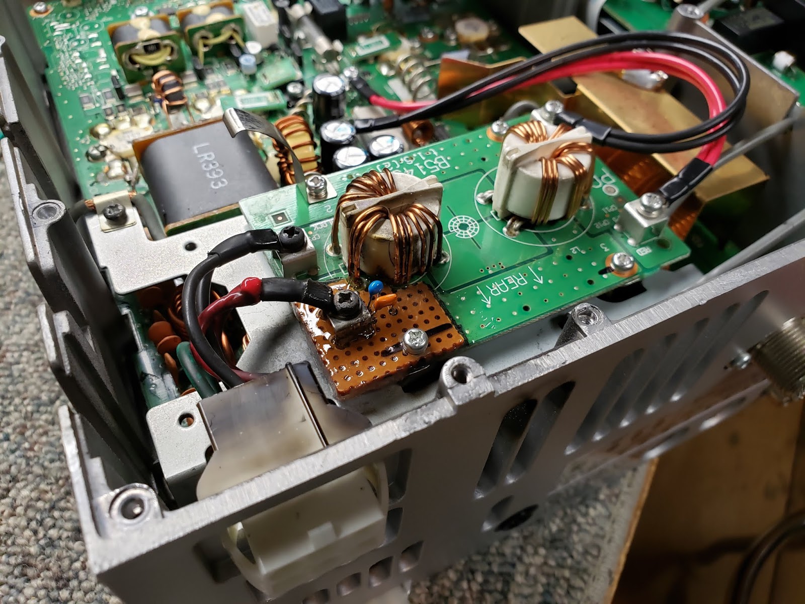
This post is about the repair of the DC power input filter board B5143D in an Icom IC-746. This is an uncommon failure in some of Icom's amateur and commercial gear of this era. The metal used in the plating of some parts will grow "dendrites" (metal whiskers) over time and cause arc-overs of some of the higher power portions of the PC boards. In this case, there was only a small distance between the high current DC positive voltage input terminal and the PCB ground trace of the power supply filter board B5143... one the metal whiskers got close enough to ground, and BOOM!! ... A short circuit appeared, and the high current capability of the power supply turned this edge of the board into an arc welder. 

Upon initial inspection it looked bad, but it wasn't too difficult to rebuild. These boards are no longer available, so replacement wasn't a simple option. I cleaned the board to determine how much of the board the fire had consumed, then used the scroll saw and cut that part of the board away. Since the damaged part was now carbon impregnated from the fire, it was conductive and had to be removed. 

Next, I cut a piece of perfboard, and bonded it to the original board with fiberglass resin. Another coat of resin was applied to the top and the bottom of the new part to better bond it to the OEM board. The new piece was then drilled and fitted with the power connector and the discrete components that were burned away. 

The repaired board was reinstalled, reconnected, and the radio was as good as new. Here's a few pics of the work...


C1 & C2 are the discrete capacitors that were blown away from the OEM board...


Finished and ready to go!

Dave WB4IUY
http://www.WB4IUY.net