Sunday, September 20, 2015

AM Spotting Tool Now Online!

http://www.qsl.net/potomacam/amspots.htm

Those of you who operate AM, there's a new spotting tool specifically for AM operations online. It's really nice, as it only shows AM sigs and info and you don't have to reconfigure your normal cluster spotting to use it. It doesn't clutter up the normal cluster with non-DX Am spots and such, and works great! Go to the following link for all the "skinny" on this cool new tool for AM operators!

http://am.w6rk.com/

AM Mode Event Oct31-Nov1 !!


If you're an AM operator (or interested in operating AM), you'll find this upcoming event to be pretty cool... It's sponsored by the Potomac AM Group and runs from 0000 UTC on October 31, 2015 to 0000 UTC on November 1, 2015 . 


Purpose: Use full-carrier Amplitude Modulation transmissions on amateur radio bands to make enjoyable AM QSOs, renew old acquaintances, meet new friends, and encourage newcomers to try AM.

1.1 Operating Period: 0000 UTC on October 31, 2015 to 0000 UTC on November 1, 2015.

2.1 Transmission Mode: All transmissions must be full-carrier amplitude modulation. A participant may contact other stations that use AM, SSB, or DSB.

3.1 Bands & Frequencies: 160 through 2 meters. Participants may contact the same station more than once per band.

The commonly used AM calling frequencies listed below (+/-) may be good starting points for AM Tailgate QSOs. Calling frequencies may vary by geographic location.

          160 Meters           1.880-1.885 MHz
          75 Meters           3.705, 3.870-3.885 MHz
          40 Meters           7.285-7.295 MHz
          20 Meters           14.330 MHz
          15 Meters           21.420 MHz
          10 Meters           29.000-29.200 MHz
          6 Meters           50.420 MHz
          2 Meters           144.270 MHz

Please note that full-carrier AM is not confined by U.S. regulations to any particular voice frequency(s), and AM QSOs regularly take place outside established calling frequencies & windows.

4.1 Calling CQ: “CQ AM Tailgate” and "CQ Tailgate" are suggested ways of calling CQ for this event.

4.2 QSOs Generally: It is suggested that while in QSO, participants listen for, and include, breaking stations as conditions allow.

5.1 QSY-in-30: After 30 minutes in any generally observed AM window it is suggested that AM Tailgate participants (1) QSY no fewer than 5 KHz, or (2) QRX on that frequency for at least 10 minutes. Participants who relinquish a frequency may answer AM Tailgate CQ calls by other stations on that frequency.

6.1 Logging: Logs are extremely valuable in determining participation levels and the level of interest in continuing the event. Therefore, operators are asked to submit their logs showing, at a minimum, the following information for each station contacted: Date, Time, Frequency or Band, Call Sign, Mode used by station contacted; Name of operator; and QTH. Hand-written logs or logs generated by software will be accepted. Hard copy log & summary forms are available by clicking on the links above.

6.2 Spotting: Spotting of AM Tailgate participants is encouraged using the AM Spots page at: http://www.qsl.net/potomacam/amspots.htm .

6.3 Log Submissions: Please submit electronic logs via e-mail. To submit hand-written documents by e-mail, please convert to PDF. Log & summary sheet must be received no later than 11:59 p.m. EST on November 10, 2015, sent by e-mail to:


or by surface or air mail to:


Please include a photo(s) of you in your station.

7.1 Results: AM Tailgate results shall be tallied no later than December 1, 2015. Recognition may be given on the web for participation in this event.

8.1 Contact: Contact the 2015 coordinator at:


8.2 AM Tailgate rules & forms will be final as of October 1, 2015 unless otherwise indicated. Please submit comments & suggestions.


For more info, go to the official event webpage at:

http://www.qsl.net/potomacam/amtailgate.htm


Saturday, July 11, 2015

Repairing the Icom IC-211


This was another late sleepless night project... Back during this past winter, I accidentally blew the receiver sensitivity out of my old Icom IC-211 2 meter SSB rig while operating on 160 meters at full power. I never turn the IC-211 "off"...maybe a mistake. The 160m antenna is up on the tower at about 100', the 2m SSB antenna is about 15' above that. I've left the 211 on 144.200 for years, no matter what other band or power I was running...but that roll of the dice finally caught up with me. 


I broke the rig open and started poking around. It had slowly developed a short list of problems, but nothing that stopped it in it's tracks like this blown front end. Using my signal generator, I capacitively coupled a signal on 144.200 mhz into the 1st RF amp stage. I found I had plenty of system gain when the signal was injected at the drain, but almost no gain when injected at the gate. A quick voltage check proved there was almost no current flowing in the device when signal was applied. It seems that the  old 3SK40 dual gate N-channel FET in the 1st RF amp stage that was toasted.


Junk box time!! I dug around in my workshop a bit, to try and locate something suitable from 35+ years ago.. That's an old part from the 70's, but I had 1 piece of ELM222 (similar device) in my parts bin (much to my surprise!).  I removed the old dual gate n-channel FET and soldered it in. I set up the signal generator, opened the service manual PDF, and gave it a full alignment. Wow!! Sensitivity was a little better than before, and I was very surprised as how hot the receiver in this 40 year-old radio is. I have a bunch of service manuals and such online for my own use, to minimize paper, and in case someone else needs them. You can find them at http://207.126.49.184/wb4iuy/radio/wb4iuy6e.htm .


While it was open I replaced the dial lamps, cleaned the optical chopper in the VFO (the VFO operation was a little erratic), and sprayed out the controls.


She's back in the shack and VHF contacts like nothing ever happened. It's definitely receiving better than before, and working pretty darn good for a 40 year old radio!

Dave WB4IUY
http://www.WB4IUY.net


Thursday, February 26, 2015

Announced DXPeditions Webpage


Many of us in Ham Radio like to chase DXPeditions to work those 'rare ones'. I'm gonna share a tool with you I've used for years that you may or may not be aware of. NG3K built and maintains one of the most comprehensive listings of DXPeditions I've ever seen. You can see what was, is, and will be active for the current year. You can click on the active operations and see spots for just that call without having to fiddle with filters in your DXcluster interface. Very often there are links to other info on the DXPeditions. 

I use it all the time to keep up with what's going on and what's coming up. You can see his page at: http://ng3k.com/Misc/adxo.html .  

I also have it embedded in my website at: http://207.126.49.184/wb4iuy/radio/wb4iuynew8d.htm .

Dave WB4IUY
http://www.WB4IUY.net 


Sunday, February 15, 2015

Working the K1N Navassa DXPedition...

The K1N Navassa Island DXPedition is nearly finished as of this writing. It was the first time Navassa Is. has been active in over 22 years. Here's what I got during their activation:


It was very well run, in my opinion, and was very enjoyable for me. I happened to be home sick during this time, and since most of my contacts were via CW & RTTY, I didn't have to use my voice much. Some contacts were quick and easy, others not so much. I think my 30m CW contact took about 4 hours and spanned a 3 day period...but I finally got through :-)

My "hat is off" to those on the DXPedition team, they certainly had to tolerate their share of intentional QRM and jamming. I think the worst case of jamming and intentional interference that I saw during their activities came from a group that came down and intentionally parked right on the K1N operating frequency of 3.725 just shortly after 03:00Z on 2/12. Since K1N was operating split, callers were all over a piece of the band from about 3.735 to about 3.765. It seems that a small group of people have a net on "their" frequency of 3.765 each night and claimed they had been on that frequency every night for the last xxx years. So, in their minds, it was OK to come sit on top of K1N and whine, complain, and moan for quite some time and totally disrupt the operation. K1N simply moved down about 5 khz and kept on rolling, but the complainers didn't know this, and continued their tomfoolery for a while longer. Oh well, after they told everyone off about how the DXPedition should pick a different frequency and various other fine points of operation, they moved on and all continued. 

I worked a "K1N" station on 12m CW on the 11th, and never saw it appear in the logs. I was listening to hear and maybe "rework" them later in the week, and read that there had been a pirate on 12m CW and many folks worked him, but didn't actually work the "real" K1N. I think I'm one of those people, hahahaha...

It was an entertaining DXPedition, one of the more enjoyable ones I've worked in quite some time. Thanks to the KP1-5 project team for this awesome event. There's lots more info online about this, including photos, videos, online log check, various news bits, etc at http://navassadx.com/log.htm 

************************************************************
UPDATE: 2/23/15: A great closing interview with K1N is at http://www.mdxc.org/k1n-interview-for-mdxc-by-w0gj/


Monday, February 2, 2015

Converting Computer Supplies for Ham Radio use


The one thing almost every radio amateur needs is a 12vdc power supply. They're great for powering radios & projects in the shack. There are many various brands on the market that are ready to 'plug-n-play'. I never seem to have enough of these things for the shack and home workshop...

Most of us have junk home computers that have been pulled out of service, know someone who has this stuff, or see them at ham fests & swap meets for cheap/free. I had seen lots of little bits of information scattered around the web on the conversion of old computer power supplies for use as a 12vdc bench supply. These are typically light weight switch-mode designs, and can produce a tremendous amount of power for their size. The typical 250w supply can generate a solid 20+ amps of clean, well regulated power, and only takes a little work for the conversion.


You'll need a few basic bits to make this project work. All of this is easily found at Radio Shack, in junk radios, etc. You need a nice set of black & red binding posts to mount on the power supply for your external connections, a resistor of between 3 and 5 ohms @ 20 watts or more, a 270 ohm 1/2 watt resistor, a LED to mount through the cover to show "on", a couple of solder-type terminal strips, and a SPST toggle switch rated at about 2 amps or more.

I started this project with an old junker 250w power supply I pulled from a donor computer. The first order of business is to clean it well...these supplier are dust magnets and usually full of lint and dust. I opened this one up and blew it out with compressed air, and made sure to clean the fan as well.


Next, we need to group all of the wires together by color. I start by cutting the connectors off of the ends of the wire bundles. There are several wires that are black, orange, yellow, red, green, and grey. You may find some other colors, they won't be used, so go ahead and cut those out. You'll remove all of the orange wires, they are for a 3.3 vdc circuit that will not be used. If I can get to the bottom of the circuit board easily, I like to desolder them. Othersize, insulate the ends and pack them away, or clip them off at the board. Remove all but 1 of the red wires. Remove all but 5 of the black wires, and all but 3 of the yellow wires.


Now, it's time for a quick test of the supply. Connect your 3 to 5 ohm loading resistor between the red wire and one of the black wires. This fools the supply into thinking it is plugged into a motherboard. Connect the toggle switch between the green wire and a black wire and make sure it is open (off) with an ohmmeter. Connect the grey wire to the anode of your LED (usually the long lead), and the other side of your LED (cathode) through the 270 ohm resistor to one of the black wires. Connect a DC voltmeter to one of the yellow wires and one of the black wires. Make sure none of the other wires or touching each other or the metal case of the power supply. BE CAREFUL, LEATHAL voltages are present...plug the AC line cored into the power supply, and flip your toggle switch "ON". If all went well, you'll measure about 12 vdc between the yellow wire and the black wire. Great! Now, power everything down, disconnect the AC line cord, and wait about 10 minutes for the caps to discharge.


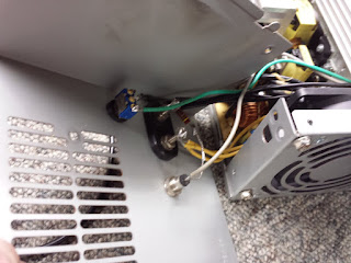
Let's mount some hardware! Pick a spot on the case or cover the you can mount your binding posts, switch and LED without it coming in contact with the internals when assembled. You'll also need to find somewhere to put the 3-5 ohm 20w resistor that you have connected to a red & black wire. I like to install a couple of terminal strips to mount the resistor so it is suspended for a little air cooling. You can see what I did in the photo, but since there are a zillion variations on the internal layout of these things, you can get very creative here. In the next photo you'll see where I mounted the binging posts, LED, and switch in this conversion. Some folks like to install fuse holders, but since all of my projects and gear have inline fuse holders, I don't bother with it.

You'll bundle 3 yellow (+12v) and 3 black (-) wires together, and connect them to the red and black binding posts. If you clip these wires to only the length needed, you'll fine that 3 conductors are ample for 20 amps of load current. The black wires should be connected to the black post, and the yellow wires should be connected to the red posts. You can use more wires if it makes you feel better, but I've tested a lot fo these and have never measured any significant voltage drop at well over 20 amps.


Put it all back together and make one final test. You'll need to always make sure the power switch is "OFF" before you plug the supply into AC, because a safety circuit in many of them will not let the supply power up if the power circuit is "ON" when the AC is connected. I test these with a simple load made of a string of parallel connected conventional light bulb sockets with a string of 50w 12dv RV lamps. I tested this supply at 25 amps continuous for 15 minutes and it barely got warm, and the difference in voltage between watts of load (4.16 amps) & 300 watts (25 amps) was less than .2 vdc.

One side note...while I can't speak for all of these supplies, I've intentionally blown several by overloading to witness the end result. In every test, the output simply dropped to 0 vdc, so I've never bothered to add a crowbar circuit like found in most linear supplies.

I hope this helps some of you build a few 12vdc supplies for your shack or workshop!
Dave WB4IUY
www.WB4IUY.net