I've been in Amateur Radio since 1974, and still find new and interesting things to do. I like to build, restore, and operate on the air. This blog has been running for many years, so be sure to check out "Jump to Posts on Specific Topics" in the RH column to drill down and find lots of stuff. Visit www.WB4IUY.net for the lowdown at WB4IUY. Email me at wb4iuy@gmail.com if you have any questions.
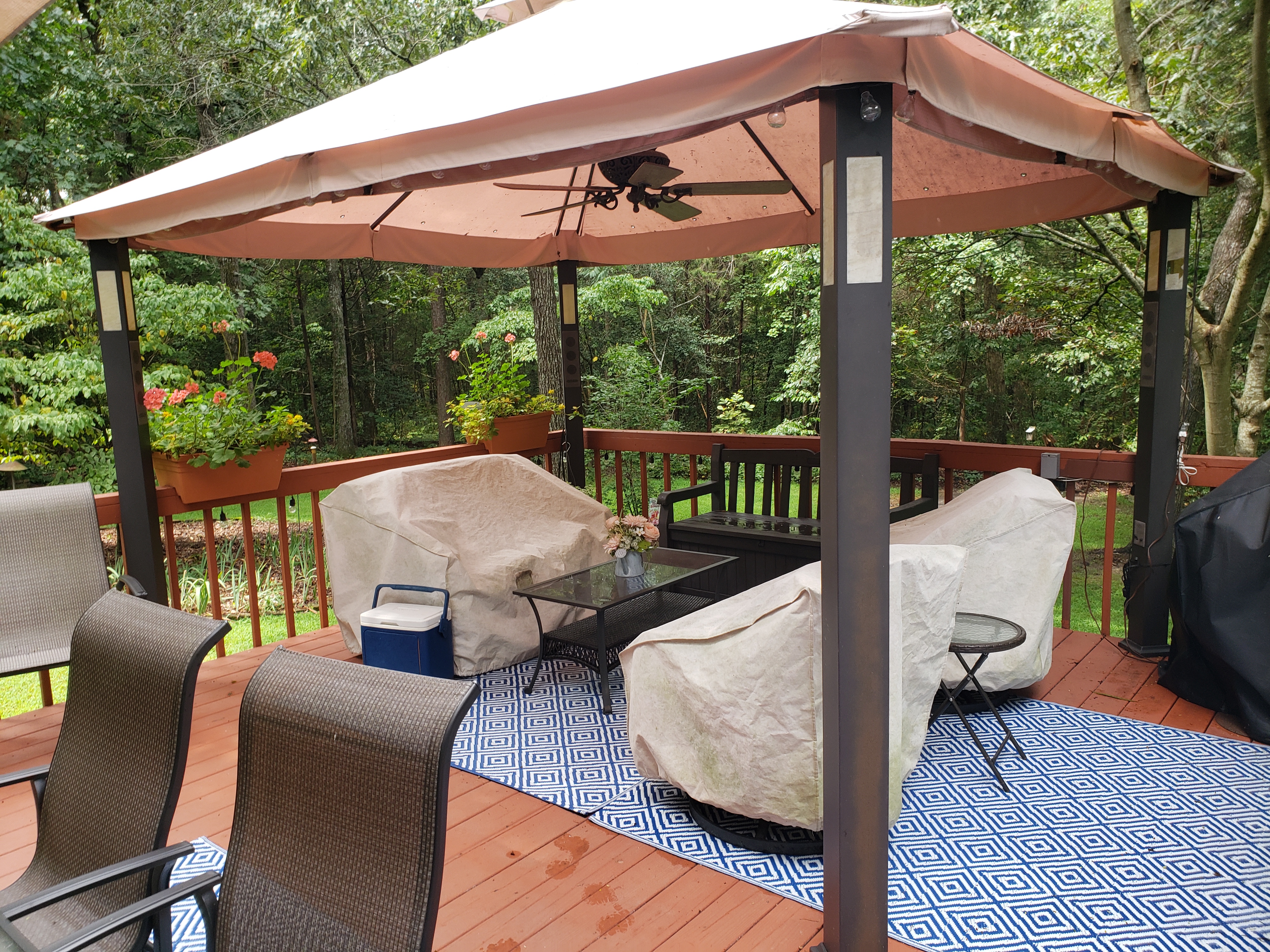
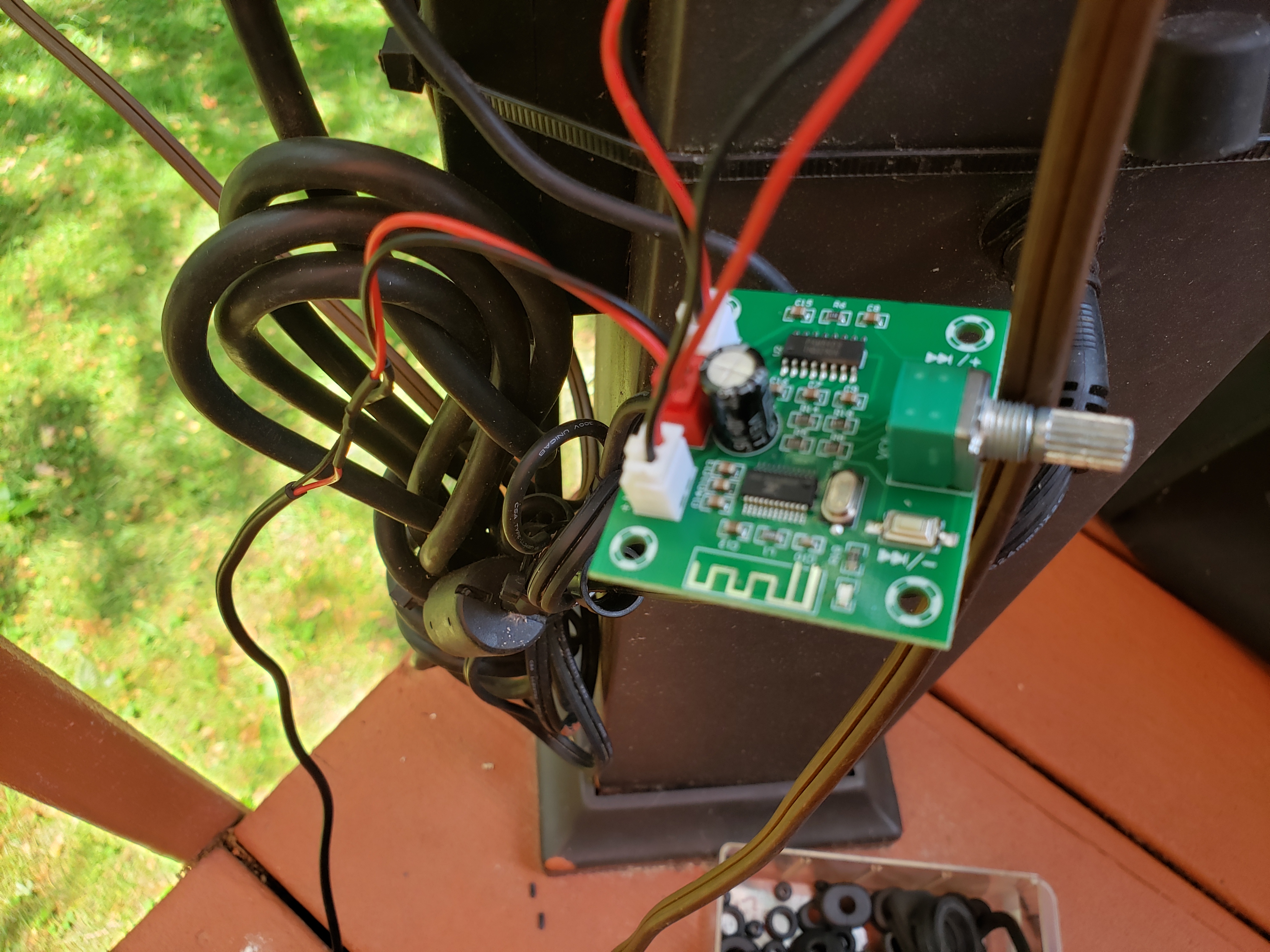
We enjoy our Gazebo on the back deck. We've had it installed since around 2012. It has lighting, a ceiling fan, and a bluetooth receiver with speakers in each vertical support pole. This year, it stopped working. After a bit of investigation, I found the receiver board was destroyed from water contamination. A little searching on the web and I found a small bluetooth receiver with a built-in 5w amp for $6 (!!). I ordered that, and spliced it into the original speaker wiring. It required 5vdc, so I hacked in an old cell phone charger with 1a output at 5vdc, put it all in a plastic ziploc bag, and stuffed it into the post with the bag's zipper facing down to keep water out. She works like new, and this was a cheap fix! Here's a few photos...
My Alinco DR-610 went deaf on vhf. It's been mobile in my truck for many years, but time for a littler attention. I found a leaky cap ate a trace on the board that supplied vco controlled voltage to the varactor tuned front end. New cap, patched trace, and she's back on the air :-) Here's a few pics to show what I found...
She's repaired and back in service. I love these old rigs!
I originally bought this Heathkit HW-101 back around 1993 from a friend at the Maysville NC hamfest. It had never been on the air, and my friend said they couldn't figure it out. It was originally built back around 1970, wouldn't work, and was put back in the box and stored away. After a little bit of work (assembly problems), it was on the air and playing like a new radio! I took it up to my Mom & Dad's lake house at Kerr Lake in NC, strung up some dipoles, and left it there...until January of 2020. I recently brought it home, and gave it a bit of a checkup, cleaning, and adjustment. It's on the air again, and just as good as it ever was.
Here's a little video after I finished up with a minor facelift on the rig. Receiving an SSB conversation on 40M at night. I have always loved these rigs, and have owned several over the years.
Here, I have the hood up. Tubes cleaned (they cool better when clean), sockets and all controls cleaned and lubricated, several mods done to improve the SSB reception by increasing the BFO osc level and reducing the IF injection at the mixer. Also replaced a bunch of carbon resistors that had shifted values over the years.
I pulled the inner lower cover and cleaned the band switch. This one also has the CW filter.
Penta Labs 6146's in the PA! I neutralized them using the cold cathode method. I also gave the rig a full alignment and made a mod to improve the carrier injection null.
Cases and face plate cleaned, and looking great for a 50 year old rig!!
Ready to move her over to an operating position in Studio B!
Wired to a non-amplified D-104 mic, the transmit audio sound great and gets good reports.
I received an Alinco DR-112 2 meter rig from a friend that needed repair. Someone had tested it and told him it needed a crystal, and since I've seen the 1st LO crystal fail in these before, I figured it would be a simple chore. Once I got into the project, I discovered that it was gonna take a bit more work than that. Here's what had to be done...
First, I noticed the 8vdc regulated source was missing from several of the sub-boards in the radio. Back-tracking a little, I found this hole in the board with several broken traces on top and bottom of the board (it's a double sided board). It looks like it might have been a mounting pad for another model, but an attempt to drill it out damaged the board...
Another view of the board from the top side. It was a little tricky, since the board had broken traces that passed under a web in the chassis casting and even split in different directions.
A view of the same hole from the bottom revealed even more cracked and broken traces that had to be repaired.
Some of the top-side traces could be repaired from the bottom...
Some of the bottom-side traces could be repaired by jumpering on the top...
Once the 8vdc connections were restored by repairing the board, I discovered the audio output chip to be destroyed, and replaced it.
When the audio output chip failed, it placed 12vdc on the 6vdc rated output coupling cap and blew it. I found it to be shorted.
Once audio was restored, I moved on to replace the memory backup battery. Someone had made attempts to replace it, and broke the connections on the board. I removed the broken clips, soldered a pigtail directly to a new battery, insulated the battery, and stuck it in place with some double side tape. The blue cap to the right of the middle of my finger is the new audio output coupling cap I installed, it's a 16vdc cap and shouldn't fail again...
After all that, I discovered the memory would reset itself just by tapping on the face of the radio. I removed the plastic faceplate and discovered a bad solder connection on the reset button )nearest to the mic jack).
Odd thing...this reset button is not accessible from outside of the radio...no pinhole for a paperclip, no trick access beside of an existing button, nothing. Odd.
Here she is, back in operation!
Here's the audio output coupling cap on the schematic...
Here's the data sheet from the mfg of the audio chip, showing a typical test circuit for that device...
Here's the parts layout of the main board, showing the physical location of the audio output coupling cap. This radio was a bit tough to work on, since the only schematic I could find had none of the notes in English. The Service manual, Operators manual, and the schematics are on my website at www.WB4IUY.net
Here's a short video clip after the repairs were completed.
The old Diamond X-500 2m/70cm vertical is finished, reassembled, and
up on the test mount. This one had a rough life... Back in 2016, the
antenna had quit working. When the tower fell in April '16, the
fiberglass portion also got snapped off just above the aluminum mount. I
tossed it in the scrap antenna pile until a later date. Fast forward to
May of 2018, I finally got to it while rebuilding all the damaged
antennas,
The metal base had to be cut away with tubing cutters to
gain access to the base loading coil, as the threaded section had
become seized. During disassembly, I discovered the series and shunt
capacitors in the base were toasted. Closer examination revealed the top
part of the fiberglass enclosure was split and the metal cap was smutty
black...I'm guessing it had taken a lightning strike. The condensate
drain hole was also plugged up with _stuff_, so that was cleaned out for
proper drainage.
The
capacitors were originally some low voltage style. I replaced the series
cap in the feed with a nice 10pf 2.5 kv version, and fabricated the
1.5pf shunt cap by twisting two pieces of wire with 600v insulation,
while reading the value with a capacitance meter. It was all cleaned up,
the contaminated foam removed from the coils, the stacking couplers
were sanded to remove crud, the top fiberglass section was repaired with
fiberglass resin, a pvc sleeve / splice was installed over the broken
section at the bottom of the fiberglass enclosure (radome) and 'glassed,
and the bottom aluminum section was brazed back together with low temp
aluminum brazing rod and a propane torch.
I got it up on the
test tower this morning and ran some tests, and all was well. SWR match
is good, and some on the air tests proved that it was working pretty
good. I'm ready to install the decoupling elements, and get it up on the
tower on a sidearm (I'm not top mounting it, these things seem to be
lightning magnets when put on top of tall towers!).
Parts of the antenna are in this pile of scraps...
Internals out of the radome, partially cleaned up...
Nasty couplers...
Damp contaminated foam on the coils had to be removed...
Had to use a tubing cutter to cut the bottom off, to gain access to the base loading coil.
Yuk... corrosion and ratty looking caps...
Shunt cap blown apart...
Shunt cap...
I
split a piece of pvc pipe to stretch over the fiberglass tubing, made
clean cuts on the broken fiberglass, wetted the parts with fiberglass
resin, and assembled...
Fiberglass resin applied to all parts...
Fiberglass cloth laid over the splice...
Fiberglass CSM (chopped strand matte)
Base cleaned up, ready for reassembly...
1.5pf cap (dicky) fabricated and installed (in red).
10pf
series cap installed... I slipped a piece of thick heat shrink over
this assy, before reinserting it into the aluminum housing...
All
reassembled, I used GE silicone caulking to seal all of the joints, and
bolted it to the top of the test stand in my back yard. SWR was good,
and it seem to work OK. Another antenna resurrected from the scrap pile