This is a common problem for what is otherwise, a wonderful radio. This rig uses a CCFL back light behind the LCD display, similar to that used in the IC-756. The PNP transistor in the back light inverter circuit has practically NO heat sink, so the lower level the light is operated at, the hotter the device operates. In most of the 746's, it's not a matter of "if" it will fail, it's "when" it will fail.
No worries, it's not a complicated repair, it just requires good eyes and patience :-) Here's a few pics of one I did for a friend locally. I replaced the device with a transistor with higher ratings, and heat sinked it to the metal inverter shield.
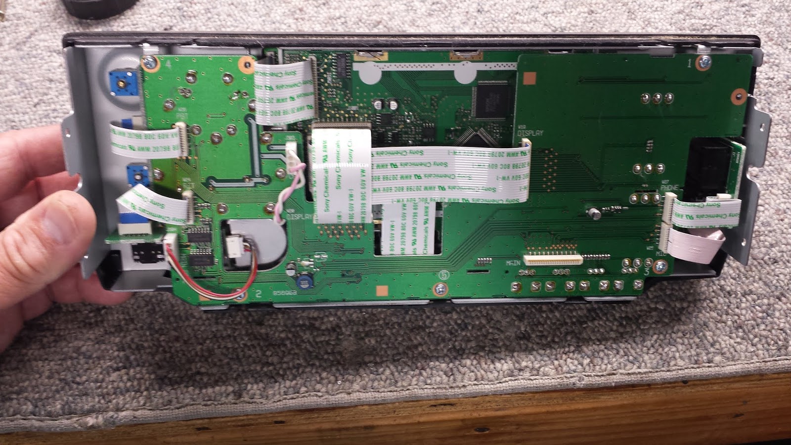
You have to really dig into the rig...here, I'm in the process of removing the front panel assembly...
Front panel removed from the rig...
Back of the front panel...
Started disconnecting cables between the front panel and sub-logic boards...
Outer front panel (face of radio) removed...
Front panel with radio face removed...
PCB with back light inverter cover removed (upper RH side of board)...
The device in the lower RH side is the failed PNP transistor. It is soldered to a tiny pad of copper board, isn't even sinked to the rest of the copper. I remove that, remove the shield, drill a hole in the shield, attach a new device to the shield via thermal grease, and reinstall...
Here, you can see the device attached to the wall of the shield, with the shield re-installed. I use leads to extend the device back to the circuit board pads where the OEM part was soldered...
A view of the attaching screw for the new device, through the shield. The shield makes quite a nice heat sink for the small amount of heat generated.
A view inside of the inverter compartment, exposing the new output device.
Power up testing on the new CCFL back light regulator. I set the internal range for very little adjustment, with the lamp at about 50% output.
Back in the shack of my friend and local ham. Looks great!