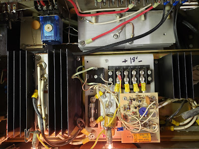
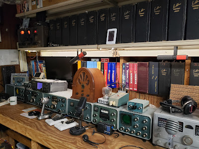
This is a quick "walk-through" of a Yaesu FL-2100B amplifier that I converted from the old (expensive) 572 tubes, to the very durable (and inexpensive!) Russian GI-7B ceramic triodes. It's not a difficult conversion, and I've included the schematics at the end, of the tuned input and other mods to make this work. These amps will now run about 800 watts (depending on band) with these easily obtainable tubes. The GI-7BT is the very ruggedized version that was designed to operate in Russian military tanks!
First, I pulled all of the stuff associated with the 572 tubes and sockets out, except for the tuned input. I've seen several done by mounting the tubes horizontal and eliminating the tuned input, but I wanted to retain the input circuitry. I mount the tube socked in the holes where the fans were, for a vertical installation. I strip all wiring associated with the 12vac winding on the transformer, so the 12vac fil windings are above ground and only pass through the bifilar fil choke to the tube. Flip the amp on it's side, and power the fils for 24 hrs with no hv on. Temp fan seen on one of the pics. This helps regetter these NOS tubes.


With no HV, I engage the t/r relay with 12vdc, place a resistor from the tube cathode to ground, and change caps in the tuned input to match the input to these new tubes. I built a little variable cap stack and clamps to the frame, disconnect the caps in the tuned input, and adjust for a minimum SWR, The measure the caps at their settings, and change components accordingly. a 51 ohm resistor is used to simulate the tubes input imp, and my MFJ analyzer is used to measure the input imp.
Similarly, I use 1900 ohms from the plates to gnd (no HV!), engage the ptt relay only, and adjust the tank circuit accordingly. You'll notice some of the plate padding caps moved and/or changed. This gets things pretty close before I actually put fire in the wire :-)
We're now getting close to actually going online. I install a HV interrupter relay under the bottom, connected to the standby switch, to keep HV off the tubes until 3 minutes (at least) of warmup.
I install a doubler on the old 6.3 vac (originally the fil circuit, no longer) windings to provide 12vdc for the switching relays.
Here is a relay installed, activated by the standby switch, to open the low end of the HV winding to the hv doubler. This interrupts the HV circuit until the tubes are warmed and ready to come off of standby.
Here you can see a pair of small 1-1/2" square fans installed under the chassis to keep the tube sockets cool. The GI-7B filament terminations can get quite hot.
The fan seen in some of these photos is not a permanent install. I installed a pair of 4" whisper fans in side, blowing right across the tube coolers, and powered from the 12vdc circuit. This top fan was just for long duration testing.
In this build, I use two pieces of plate glass between the RF choke and the upper metal RF shield. I moved the rf choke closer to the lid during the build, and this was required to eliminate arcing. In later conversions I leave the choke in the OEM locations, and space the tubes further apart to allow for clearance. Glass no longer required :-)
In this pic, you see the additional RF choke I installed in series with the plate choke. This moved the resonances of the choke assy clear of the various ham bands needed.
These following charts show some of the tuned input and tank capacitor changes needed for the GI-7B tubes.
This makes for a nice, clean, and quiet running 800+ watt amp with inexpensive GI7B tubes. You can also use the GI6B, GI7BT, and GI9B tubes in this mod. Dave WB4IUY
http://www.WB4IUY.net


