Monday, February 17, 2014

Hy-Gain Hy-Range 1

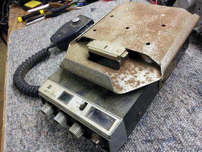
Another one out of the junk pile... Hy-Gain Hy-Range I. This is the CB I had in a '61 Chevy pickup, back in the late 70's. I picked up another for parts up at a swap meet somewhere, been in my attic since around '93. Bad channel selector, blown lamps, broken wires in the mic cord, bad speaker, rusty cases. Finally finished it, probably wasn't worth the effort, but it's a nostalgia thing for me

Found a little info about Hy-Gain. Looks like this might have been made before 1975, since the Hy-Gain III came out in '75. Here's a little info in the radio museum... 

https://www.radiomuseum.org/dsp_hersteller_detail.cfm?company_id=9119&fbclid=IwAR0P7w2ZcsApD21dZE9Ebpzmh1vzXXlcz6Dpzhy-ycSgTIDTYSvGKowrbKg


Before...


After... I have this mounted on a bracket near my workbench, in operation most days. 


Saturday, February 15, 2014

Johnson Messenger III

This is an old Johnson Messenger III I picked up at a swap meet. I had one like this on the air, back around 1977 or so. I plan to restore this one at some point, so I started this page to build on when I get to it. 


Friday, February 14, 2014

Midland 13-862B

I cleaned up this old Midland 13-862B CB mobile rig and got it back up to speed. Typical stuff, lamps, cleaned the controls, cleaned it well, alignment. Nothing special, but kinda special to me. It was my mom's mobile back in the mid-70's, when she dispatched for my dad's plumbing & heating company over CB radio. It's been in the attic for probably 20 years or more.


Before...


After...


Tuesday, February 11, 2014

Robyn 240D


These are pretty cool little radios. All tube-type, except for the PLL circuitry for frequency synthesis. A friend picked this rig up, and it needed some help. Lots of little problems needed attention, but nothing major. There's practically nothing published on this rig for mods (except for one bogus mod that is all over the web), so I set out to comb through it and fix a number of problems and upgrade / improve a few things. You'll need a schematic or Sams Photofact to locate some of these items, but the work is pretty straightforward. 


Power supply & modulation issues : 

Once working correctly, I noticed this rig (and another my friend brought to me) lacked low frequency response in the transmit audio chain, and didn't have enough headroom in the power supply to allow for 100% positive modulation peaks. Negative peaks were 100% easy, while positive were clipping at about 80%. Here's the list of changes...

1- Install a .5uF 25vdc cap from pin #3 on V6, to ground. Keep leads short. + terminal of cap to pin #3. 


2- Bypass R27, 100 ohm resistor in the 278vdc source, this raises it to about 290 vdc.


3- Lift one end of R28 1K 5W and install a 150 ohm 5W resistor in series, or replace it with a 1150 ohm 5 watt resistor. This restores the 211vdc source to the correct voltage, after the mod in step #2 above. Actually, it raises it from 211 to about 218, and improves the rx sensitivity. More on that, later...


4- Relocate C905 1uF 160v cap from across R906 1K, to across R904 6800 ohm. (-) of cap to the L907 end of R904.


5- Bypass R906 1K. 


6- Change C601 to .1uF 500vdc disk


Receiver sensitivity: 

In step #3 above, I stated to lift one end of R28 1K 5W and install a 150 ohm 5W resistor in series, or replace it with a 1150 ohm 5 watt resistor. This restores the 211vdc source to the correct voltage, after the mod in step #2 above raises it to about 225vdc. This restores the primary receiver strip voltage (normally about 211vdc) to about 218. I have many ham band receivers that place 230vdc or so on those same tubes, with no long term effects. This simple mod improved the receiver sens from .5uV @ 10dB SINAD, to about .3uV @ 10dB SINAD, a very noticeable improvement.

The following changes brought the receiver sensitivity up to better than .1uV @ 10dB SINAD.


Change R106 from 47K to 220K


Change R201 from 680 ohms to 1200 ohms...


Install a 56k resistor in parallel with R303 (100K)


Delta Tune issue: 

I've seen many comments on the web about users having to operate the receiver with the delta tune at about the 3 o'clock position for best reception. I found a 10k ohm 1/2 W resistor installed from the wiper of the delta tune control, to the high side of the pot, will move the varacter voltage to about 4.5vdc and bring the rx center frequency spot on with the delta tune control at 12 o'clock. You could also install a small 15k pot in the same place as the 10k resistor I mentioned, and dial it in that way. The issue is caused by drift in the 15mhz crystal, and padding it results in osc instability...this seems to be the best and most stable approach to correct the problem. 


HEAT!! : 

 These radios run HOT!! I installed a small 12vdc fan inside of the radio, to pull heat out (never blow cool air in, simply pull the hot air out slowly to cool the rig). I picked up the low voltage DC supply for the fan at the high side of R191 10 ohm, and ground directly to the chassis. I installed my fan on the inside, it is nice and quiet, and works great. 


  Instant On: 

Another problem with heat, is where Robyn decided to keep the radio mostly powered up all the time, to give the illusion of it being "instant on". I really don't like this, and want the rig off when the switch is set to "off". This also keeps the rig cool when you're not using it. 

1- Locate the red and brown wires that connect to the power switch. Trace those around the center of the chassis and back to their connection points near the main power socket on the back of the rig. Clip them from their connection points on the terminal strips, and connect a jumper across where they were connected. 


2- Pull the ends of the red & brown wires up and towards the rear power socket on the back of the rig. Locate the (usually yellow) wire coming from the power socket pin #3, and clip it free from the terminal  strip. Connect the brown wire to the terminal strip where you clipped the wire from, and connect the red wire back to the free end of the wired coming from the power socket pin #3


Now, the rig will truly shut down, when you set the power switch to "off", and help with keeping the rig cool.


***MORE TIPS***

- Swap the 6BQ5 modulator tube out with a 7189. I use a SOVTEC EL84M for even better modulator performance.  


- Replace the 6GH8A tube out with a 6EA8A tube. It's much more stable over time than those flakey 6GH8A's, easier to locate, and has a little more output for the reference oscillator.


Monday, February 10, 2014

President Dwight D

Having fun digging out some of the barn finds and such from the junk pile in my attic. I picked up a President Dwight D CB base station sometime in the early 80's, don't remember when exactly. Got in a deal with some other radios and it had a few problems, mostly screwdriver related. Tossed it on the 'to do' pile, and never did it. It's been in the attic of our home since we bought it and moved in back in '93. Repaired the squelch circuit, cleaned all the controls, aligned the receiver, cranked up the audio a bit and tuned the transmitter. Clock is bad, and from what I hear, that's not uncommon. Wired one of my Turner +2 desk mics to it, and it plays good. After a lot of scrubbing and cleaning, I found a there was a pretty nice looking rig in there. It's just a 40 channel AM rig, but still a nice CB radio from 'back in the day'!


JPS ANC-4 finally repaired!


My XYL, Debbie AC4QD, bought this for me as a gift back around the early 90's...don't remember when, exactly. It came from Bill K4BWC (now SK) at Omega Electronics, and was a huge help at our apartment ham shack. We were plagued by all sorts of locally generated noises and interference, and this thing did the trick!

We bought our home in Youngsville in '93, moved , and set up the ham shack at our new location. All was well until a big lightning strike in '97 that destroyed nearly every piece of gear we had, including the little JPS ANC-4. I repaired most everything, but this one got tossed on the shelf in the workshop, unrepaired. Time moved along. Our new location was much better and very few noises bothered us. Every now and then I'd think about it when spurs from the wide screen TV or laptop would bug me.


Recently, I decided to pull it down off the shelf and revisit repairs to it. The damage looked worse than it really was... a melted & destroyed relay, a flamed out pair of 100 ohm resistors, some minor curcuit board damage, and a pair of blown 2N7000 FETs in the rf sensing circuit. All parts were less than $5 from Mouser Electronics.

I ordered up the parts, made repairs, and it's back in it's rightful place in Studio A, fighting away spurs from the TV and looking good. I had forgotten what a neat accessory this is. JPS has long since gone out of business, and TimeWave picked this unit up and produced it for a number of years. The TimeWave circuit is basically the same, with only a couple of improvements over the original JPS design. The parts layout on the PC board are the same, even the cabinet is the same. I see these on the ham radio swap forums for $75-$125, and it seems that all parts are still available for repairs.


If you live in a location with locally generated noises and interference that hamper your HF/6 meter  operations, this is a good solution. It uses a built in telescopic whip antenna for noise reception, and has a port on the back for an external antenna if your noise is coming from a source that's not physically in or near  the shack. It samples the primary antenna and the noise antenna, and uses a phase cancellation method to eliminate the unwanted signal. I can even hear signals that were previously below the interfering signals.

When you see these at the swap meets or online, remember that it's a great accessory for your shack, and works quite well at removing those aggravating spurs and extraneous signals that most all of us deal with from time to time. I'm happy that mine is finally back up and running, though it took me 17 years to 'get around to it'  :-)

73
Dave WB4IUY
www.WB4IUY.net

Saturday, February 1, 2014

Wawasee 8417 One Tube Mobile Amp

This was a mobile amp that was somewhat common back around the late 1970's. It used a single 8417 tube (similar to a 6L6, but much higher output), and a pair of chopper transistors with a toroidal transformer to generate the high voltage. This is a grid driven amp, using a variable transformer input / 50 ohm swamping resistor to maintain a 50 ohm input, and a link coupled output. They work pretty good with a QRP rig on 10m, and would provide about 100w output on SSB, 50w on CW, and about 35 watts carrier on AM. The DC-DC converter in amps like this is noisy, but you could stuff it under the seat or in the trunk and it all was well. 

This one originally had TO-3 style PNP germanium switchers. They had failed (not uncommon on this model) and damaged some wiring when that happened. I drilled the heat sink for a pair of much heavier TO-36 devices, capable of handling much higher current values and better heat dissipation. The flex cable from the center pole of the relay is what switched heavy current for the power supply, and had also failed. I replaced it with a heavy piece of copper braid, as well as a few capacitors were replaced.