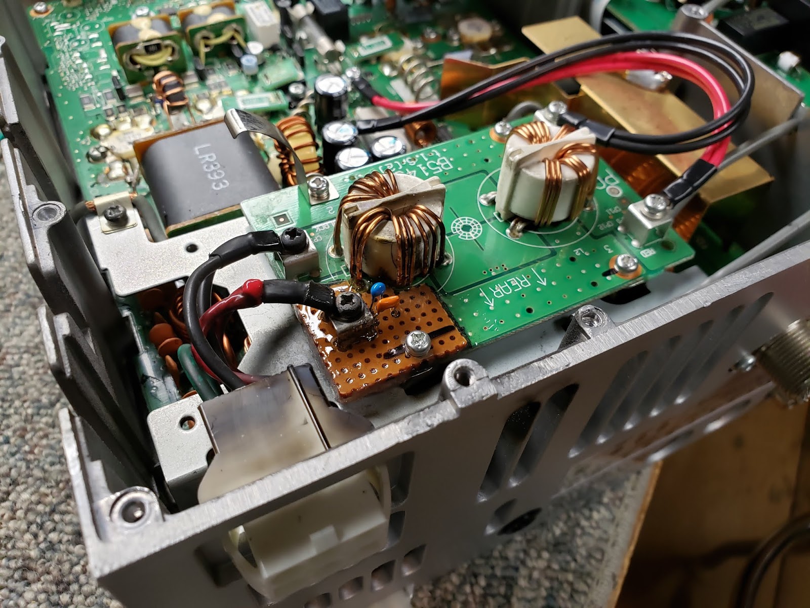
I received an Alinco DR-112 2 meter rig from a friend that needed repair. Someone had tested it and told him it needed a crystal, and since I've seen the 1st LO crystal fail in these before, I figured it would be a simple chore. Once I got into the project, I discovered that it was gonna take a bit more work than that. Here's what had to be done...

First, I noticed the 8vdc regulated source was missing from several of the sub-boards in the radio. Back-tracking a little, I found this hole in the board with several broken traces on top and bottom of the board (it's a double sided board). It looks like it might have been a mounting pad for another model, but an attempt to drill it out damaged the board...

Another view of the board from the top side. It was a little tricky, since the board had broken traces that passed under a web in the chassis casting and even split in different directions.

A view of the same hole from the bottom revealed even more cracked and broken traces that had to be repaired.

Some of the top-side traces could be repaired from the bottom...

Some of the bottom-side traces could be repaired by jumpering on the top...

Once the 8vdc connections were restored by repairing the board, I discovered the audio output chip to be destroyed, and replaced it.

When the audio output chip failed, it placed 12vdc on the 6vdc rated output coupling cap and blew it. I found it to be shorted.

Once audio was restored, I moved on to replace the memory backup battery. Someone had made attempts to replace it, and broke the connections on the board. I removed the broken clips, soldered a pigtail directly to a new battery, insulated the battery, and stuck it in place with some double side tape. The blue cap to the right of the middle of my finger is the new audio output coupling cap I installed, it's a 16vdc cap and shouldn't fail again...

After all that, I discovered the memory would reset itself just by tapping on the face of the radio. I removed the plastic faceplate and discovered a bad solder connection on the reset button )nearest to the mic jack).

Odd thing...this reset button is not accessible from outside of the radio...no pinhole for a paperclip, no trick access beside of an existing button, nothing. Odd.

Here she is, back in operation!

Here's the audio output coupling cap on the schematic...

Here's the data sheet from the mfg of the audio chip, showing a typical test circuit for that device...

Here's the parts layout of the main board, showing the physical location of the audio output coupling cap. This radio was a bit tough to work on, since the only schematic I could find had none of the notes in English. The Service manual, Operators manual, and the schematics are on my website at www.WB4IUY.net
Here's a short video clip after the repairs were completed.
Dave WB4IUY
www.WB4IUY.net