Tuesday, August 29, 2023

Another IC-756 Display Replacement

 This is another Icom 756 display repleacement using the Yuxian model # LG3202404BMDWH6N display. This is the first unit Ive done without building a separate outboard 5vdc power supply for the LED back light. After extensive testing, I determined the 5vdc regulator on the main board is more than ample to supply the new LED backlight. I go in the main menu and turn off the CCFL backlight by setting it to 0%. I also DO NOT feed the contrast voltage from the main board to the new display, these have internal thermal compensation for contrast that is more than adequate. Click "756 Display" in the menu at the top of the page to see the latest in installation notes, as I have certainly gone through a lot of different displays over the last few years. Here's a few pics and more notes...


I LOVE these radios with the blue display!!


 Front panel off, about to disassemble it for the fitment of the new Yuxian display.


Above is the new display, ready for fitment into the subframe. Size is close to original...actually, the screen is the same, but the pc board and frame are slightly larger. 


Below is a pic of the 1st board that has to be removed from the head unit. Some things are soldered between layers, so you have to take your time and be patient. 


Above, you can see the display fitted into the sheet metal subframe. I use a dremel tool and cut-off disc to trim sheet metal from the subframe. I have it marked at the top of the pic above, near me thumb, where I'll scribe a line and cut away this amount. . You can see, two photos below, where I've trimmed the metal away and mounted the display assembly. 

 In the photo below, you see where I cut a piece from the bad original display, and use it to attach the ribbon cable and interconnect to the new display.


Above, you see the new display mounted into the sub-frame, awaiting wiring. Below, I have installed the cut section from the old board and wired it to the new display unit. In this way, the original ribbon cable from the main unit to the head is still used without modification. 


Above and below, I'm testing the backlight with external 5vdc power. At this time I"ll peel away the protective clear covering and begin to reassemble the head unit. 


The last few pics show the display in testing, head unit reattached to the main unit, and in the process of setting the contract level from the main menu. The level of blue is adjustable with contract. The display has about a 10 minute warmup period, after which the display contract is stable and needs no further adjustment. The displays are more directional that the original, so you'll adjust the contrast for your taste, depending on the viewing angle you usually have for the rig. 


Dave WB4IUY

http://www.WB4IUY.net


Friday, August 4, 2023

Icom IC-7000, Won't power up...

 This was an Icom IC-7000 that wouldn't power up. You can press the power "on", and almost immediately hear a "click" from within. This is caused by the processor shutting the rig back down when certain voltage rails aren't properly detected. This is a very common problem with these as they age. Almost always caused by bad electrolytic capacitors. I've found this to be with C501 or C502 in the head unit, or both. The larger value caps are typically the culprits. Here is a link to a PDF written by another ham on the same topic. These aren't difficult to repair, should you run across one with this problem. I didn't take pics of the task, since the .PDF adequately documents it. The link to the pdf is:  

 https://www.wb4iuy.net/manuals/IC7000.pdf


Dave WB4IUY

Http://www.WB4IUY.net


Saturday, July 29, 2023

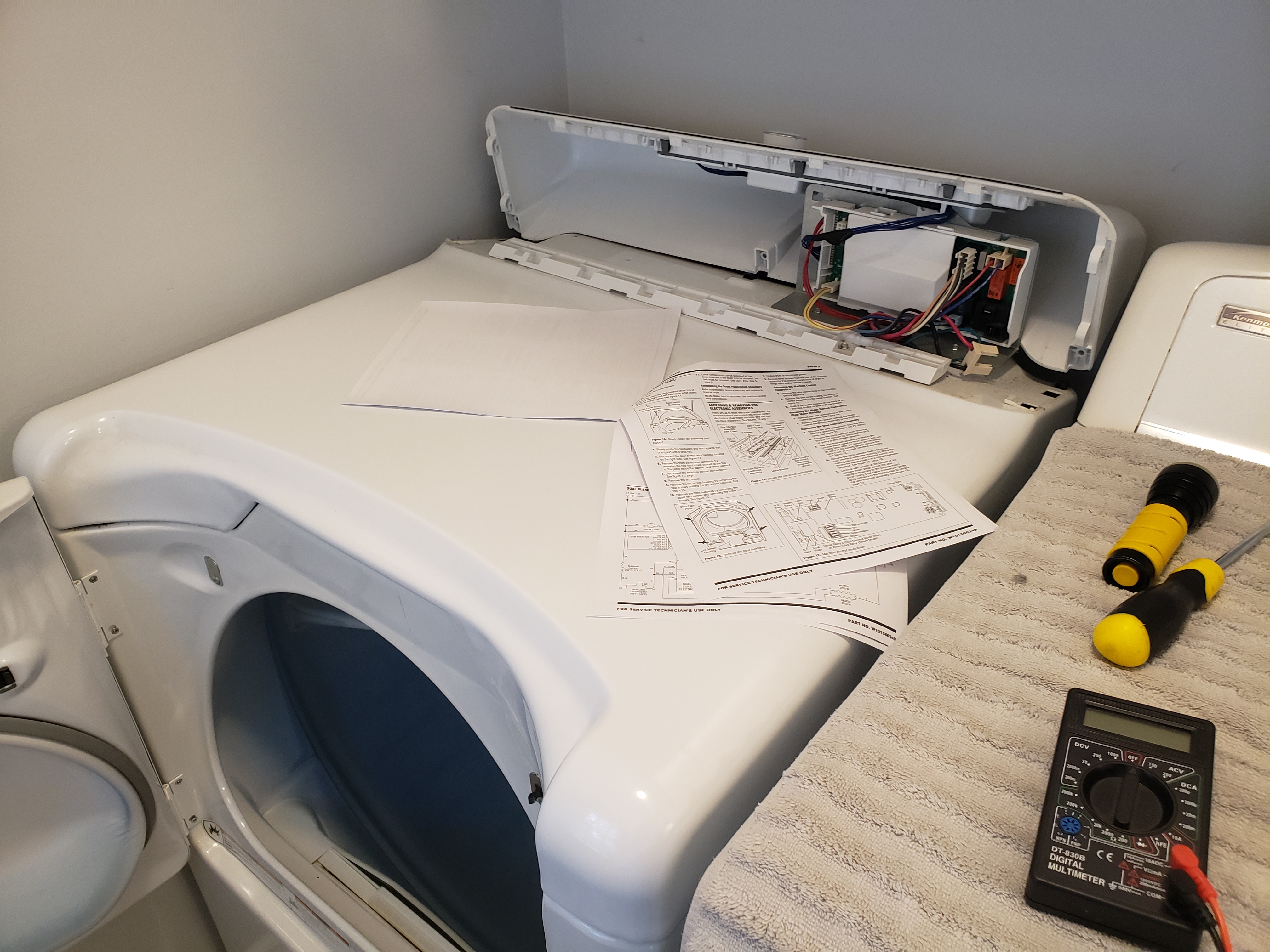
Kenmore Elite Dryer Electronics...

 Oh boy, this dryer again... Over the years I've replaced 2 heating elements prior, but this time I think I got to the root of the problem. It's a typical electric dryer 10+ years old...the element burns out, you slap a new one in for $25 or so off of Amazon, and roll on. This time, however, there were several symptoms that made me think a bit more deeply. First, for some time, it had been presenting a "low air flow" alarm, but kept running. I cleaned the exhaust path and removed mucho lint. Seemed better, but still got that "AF" alarm from time to time. Didn't think much about it, until this element burned out. When I pulled the dryer apart, the heating element enclosure was pretty warped up from excessive heat. After studying how the air flows in this system, I discovered the blower actually draws air through the heating assembly, then through the clothes drum, then out of the unit. Air flow is measured in the heating assembly. The main drum has a leather and felt seal in the front and rear that had become very worn. This allowed air to be drawn from the cabinet area and in around the drum, reducing actual flow in the heating element assy. This caused the heater to run MUCH hotter than normal, and hence failure of that. OK, so I replaced the seals and element, and put it back together. I did notice that the element has struck against the inside of the heater enclosure when it burned in half, and made a big arc mark in there. Remember that....

OK, so all is back together and running fine. No AF alarm, but it's running really HOT. I put the dryer in "air dry" mode, put an ammeter on the 220v input, and it's still pulling full power from the service...even when no heat should be on. I pulled the control board from the head of the machine, and found the relay that modulated the heating element on and off to control heat, was welded "closed". When the unit was on, full heat was being applied. I ordered and replaced the relay, and the unit went back to controlling temp. Seems when the element broke and struck the housing, it destroyed the relay contacts at that time. 

All is back together and operating properly. I know this isn't radio, but maybe it'll help someone out there, one of these days :-) Here's a few pics...


Dave WB4IUY

www.WB4IUY.net


Wednesday, July 26, 2023

Amp Supply LA-1000 Repairs & Upgrades

This is a LA-1000 sweep tube amp, made back in the 80's by Amp Supply Company. Amp Supply was a "spin-off" from Dentron, Amplifiers, and this is an upgraded model of their GLA-1000. This one was in need of work...bad caps, bad tubes, problems with the tuned input, T/R relay problems, etc. She's back up and running strong now, upfitted with Russian 6P45C tubes, new sockets and components. It'll run around 700-800 watts out, depending on band and mode. Here's some pics and a description of the work...

The first steps were to get this beast pulled apart in a way that it could be easily reassembled. Below are the tuned input board, plate choke, and main power supply boards.


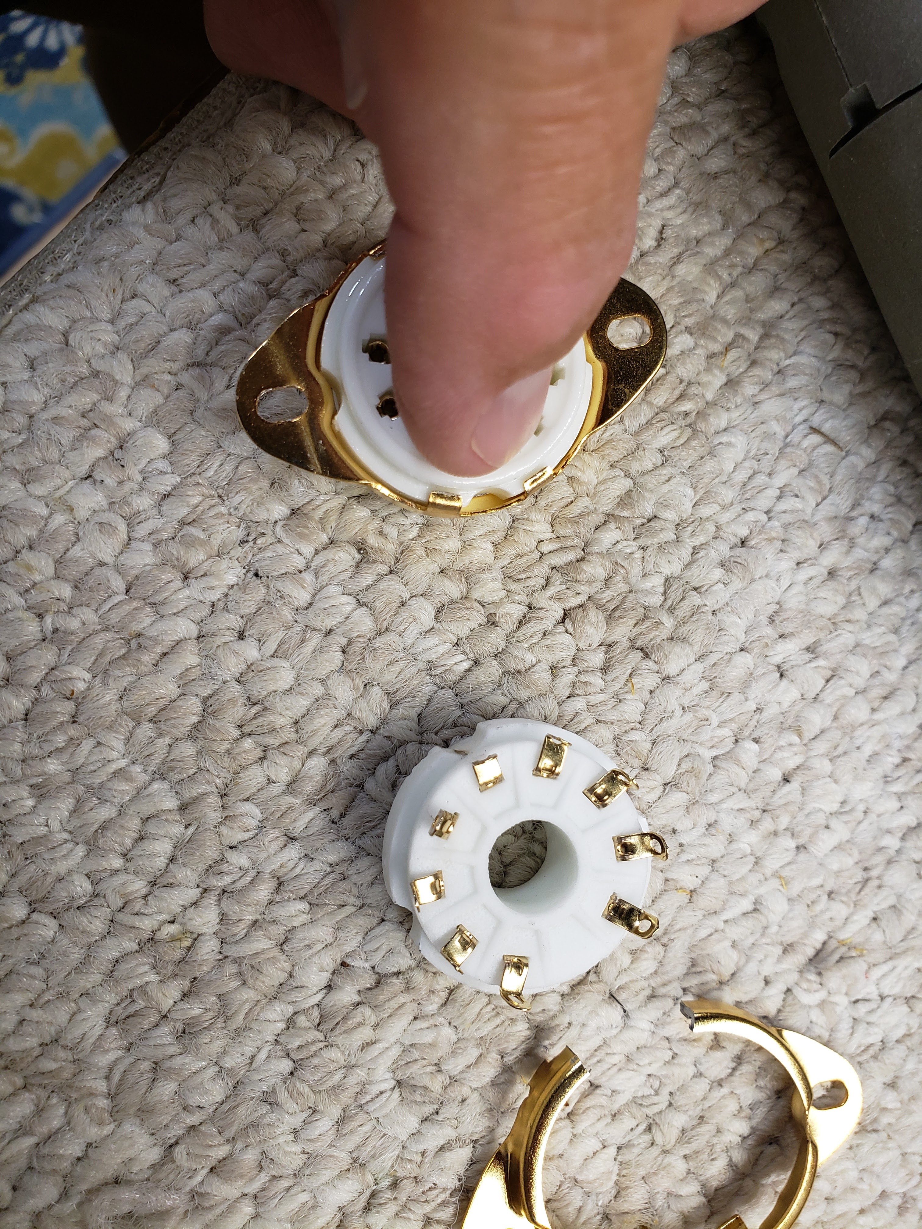
Next, the rf board has to be pulled, and tube sockets replaced. The original used 6LQ6 tubes, and didn't use pin 9. The new 6P45C tubes are larger, and require the use of pin 9. The tube pins are also larger in dia, so a different version of the socket must be installed. 


The filter caps were toast, and blown due to failed bleeder resistors. This allowed the resting voltage to rise to a value above the rating of the caps, and that stopped the parade :-)  Caps were replaced, new sockets modified and installed, and the bottom of the rf board remapped to that needed for the proper pinout of the new tubes.


The above 2 pics are the tuned input board, and below is the RF board, ready to reinstall in the amp with new bleeders, caps, sockets, etc. 


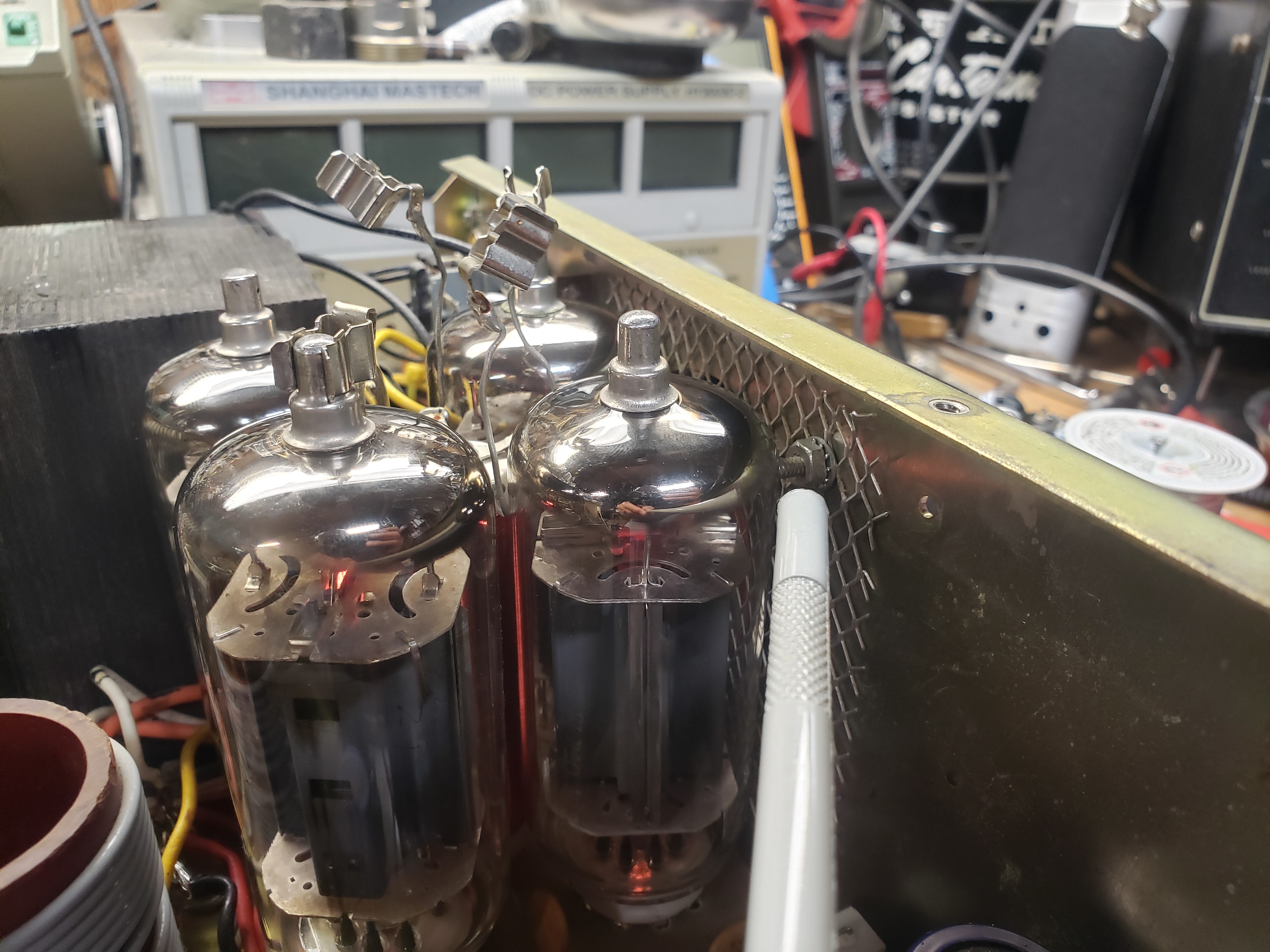
The photos below show some mechanical issues to overcome. The tubes are larger in diameter, and taller. Various bits around the inside had to be moved to allow clearance from the tubes so as to not be touching the ends of screws, etc. 


Once everything was all reinstalled and tested, I had to cut an opening in the lid and fold a perforated riser, paint it, and install it in the lid. This provided additional clearance for the top of the taller tubes. 


Here she is, back on the air and ready for many more years of operation!

Dave WB4IUY

http://www.WB4IUY.net