Thursday, February 26, 2015

Announced DXPeditions Webpage


Many of us in Ham Radio like to chase DXPeditions to work those 'rare ones'. I'm gonna share a tool with you I've used for years that you may or may not be aware of. NG3K built and maintains one of the most comprehensive listings of DXPeditions I've ever seen. You can see what was, is, and will be active for the current year. You can click on the active operations and see spots for just that call without having to fiddle with filters in your DXcluster interface. Very often there are links to other info on the DXPeditions. 

I use it all the time to keep up with what's going on and what's coming up. You can see his page at: http://ng3k.com/Misc/adxo.html .  

I also have it embedded in my website at: http://207.126.49.184/wb4iuy/radio/wb4iuynew8d.htm .

Dave WB4IUY
http://www.WB4IUY.net 


Sunday, February 15, 2015

Working the K1N Navassa DXPedition...

The K1N Navassa Island DXPedition is nearly finished as of this writing. It was the first time Navassa Is. has been active in over 22 years. Here's what I got during their activation:


It was very well run, in my opinion, and was very enjoyable for me. I happened to be home sick during this time, and since most of my contacts were via CW & RTTY, I didn't have to use my voice much. Some contacts were quick and easy, others not so much. I think my 30m CW contact took about 4 hours and spanned a 3 day period...but I finally got through :-)

My "hat is off" to those on the DXPedition team, they certainly had to tolerate their share of intentional QRM and jamming. I think the worst case of jamming and intentional interference that I saw during their activities came from a group that came down and intentionally parked right on the K1N operating frequency of 3.725 just shortly after 03:00Z on 2/12. Since K1N was operating split, callers were all over a piece of the band from about 3.735 to about 3.765. It seems that a small group of people have a net on "their" frequency of 3.765 each night and claimed they had been on that frequency every night for the last xxx years. So, in their minds, it was OK to come sit on top of K1N and whine, complain, and moan for quite some time and totally disrupt the operation. K1N simply moved down about 5 khz and kept on rolling, but the complainers didn't know this, and continued their tomfoolery for a while longer. Oh well, after they told everyone off about how the DXPedition should pick a different frequency and various other fine points of operation, they moved on and all continued. 

I worked a "K1N" station on 12m CW on the 11th, and never saw it appear in the logs. I was listening to hear and maybe "rework" them later in the week, and read that there had been a pirate on 12m CW and many folks worked him, but didn't actually work the "real" K1N. I think I'm one of those people, hahahaha...

It was an entertaining DXPedition, one of the more enjoyable ones I've worked in quite some time. Thanks to the KP1-5 project team for this awesome event. There's lots more info online about this, including photos, videos, online log check, various news bits, etc at http://navassadx.com/log.htm 

************************************************************
UPDATE: 2/23/15: A great closing interview with K1N is at http://www.mdxc.org/k1n-interview-for-mdxc-by-w0gj/


Monday, February 2, 2015

Converting Computer Supplies for Ham Radio use


The one thing almost every radio amateur needs is a 12vdc power supply. They're great for powering radios & projects in the shack. There are many various brands on the market that are ready to 'plug-n-play'. I never seem to have enough of these things for the shack and home workshop...

Most of us have junk home computers that have been pulled out of service, know someone who has this stuff, or see them at ham fests & swap meets for cheap/free. I had seen lots of little bits of information scattered around the web on the conversion of old computer power supplies for use as a 12vdc bench supply. These are typically light weight switch-mode designs, and can produce a tremendous amount of power for their size. The typical 250w supply can generate a solid 20+ amps of clean, well regulated power, and only takes a little work for the conversion.


You'll need a few basic bits to make this project work. All of this is easily found at Radio Shack, in junk radios, etc. You need a nice set of black & red binding posts to mount on the power supply for your external connections, a resistor of between 3 and 5 ohms @ 20 watts or more, a 270 ohm 1/2 watt resistor, a LED to mount through the cover to show "on", a couple of solder-type terminal strips, and a SPST toggle switch rated at about 2 amps or more.

I started this project with an old junker 250w power supply I pulled from a donor computer. The first order of business is to clean it well...these supplier are dust magnets and usually full of lint and dust. I opened this one up and blew it out with compressed air, and made sure to clean the fan as well.


Next, we need to group all of the wires together by color. I start by cutting the connectors off of the ends of the wire bundles. There are several wires that are black, orange, yellow, red, green, and grey. You may find some other colors, they won't be used, so go ahead and cut those out. You'll remove all of the orange wires, they are for a 3.3 vdc circuit that will not be used. If I can get to the bottom of the circuit board easily, I like to desolder them. Othersize, insulate the ends and pack them away, or clip them off at the board. Remove all but 1 of the red wires. Remove all but 5 of the black wires, and all but 3 of the yellow wires.


Now, it's time for a quick test of the supply. Connect your 3 to 5 ohm loading resistor between the red wire and one of the black wires. This fools the supply into thinking it is plugged into a motherboard. Connect the toggle switch between the green wire and a black wire and make sure it is open (off) with an ohmmeter. Connect the grey wire to the anode of your LED (usually the long lead), and the other side of your LED (cathode) through the 270 ohm resistor to one of the black wires. Connect a DC voltmeter to one of the yellow wires and one of the black wires. Make sure none of the other wires or touching each other or the metal case of the power supply. BE CAREFUL, LEATHAL voltages are present...plug the AC line cored into the power supply, and flip your toggle switch "ON". If all went well, you'll measure about 12 vdc between the yellow wire and the black wire. Great! Now, power everything down, disconnect the AC line cord, and wait about 10 minutes for the caps to discharge.
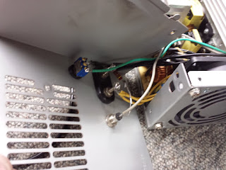


Let's mount some hardware! Pick a spot on the case or cover the you can mount your binding posts, switch and LED without it coming in contact with the internals when assembled. You'll also need to find somewhere to put the 3-5 ohm 20w resistor that you have connected to a red & black wire. I like to install a couple of terminal strips to mount the resistor so it is suspended for a little air cooling. You can see what I did in the photo, but since there are a zillion variations on the internal layout of these things, you can get very creative here. In the next photo you'll see where I mounted the binging posts, LED, and switch in this conversion. Some folks like to install fuse holders, but since all of my projects and gear have inline fuse holders, I don't bother with it.

You'll bundle 3 yellow (+12v) and 3 black (-) wires together, and connect them to the red and black binding posts. If you clip these wires to only the length needed, you'll fine that 3 conductors are ample for 20 amps of load current. The black wires should be connected to the black post, and the yellow wires should be connected to the red posts. You can use more wires if it makes you feel better, but I've tested a lot fo these and have never measured any significant voltage drop at well over 20 amps.


Put it all back together and make one final test. You'll need to always make sure the power switch is "OFF" before you plug the supply into AC, because a safety circuit in many of them will not let the supply power up if the power circuit is "ON" when the AC is connected. I test these with a simple load made of a string of parallel connected conventional light bulb sockets with a string of 50w 12dv RV lamps. I tested this supply at 25 amps continuous for 15 minutes and it barely got warm, and the difference in voltage between watts of load (4.16 amps) & 300 watts (25 amps) was less than .2 vdc.

One side note...while I can't speak for all of these supplies, I've intentionally blown several by overloading to witness the end result. In every test, the output simply dropped to 0 vdc, so I've never bothered to add a crowbar circuit like found in most linear supplies.

I hope this helps some of you build a few 12vdc supplies for your shack or workshop!
Dave WB4IUY
www.WB4IUY.net


Monday, November 10, 2014

APRS+SA on old 386


I like to use things until they're worn out, shot, kaput...I have an old computer in my shack from 1994 a Pionex 386 running Windows 3.1. For abt 20 years, it has been running DOS APRS. For many of those years, it was a stand alone APRS station, lacking many of the things that newer APRS stations have.

A few years ago, I installed Win98. I tried winXP, but this old PC was far too feeble for a newer OS in it's current state, but it runs Win98 just fine. I put it on my home network, and connected 2 TNCs. It did a great job running a local packet cluster RF port on one TNC, and my DOS APRS application on the other TNC. A year or so ago, I pulled the DXCluster RF port down, as no one was using it. The PC was left running only the simple DOS APRS program...but doing a great job at that.


Recently, I decided to see what could be done to "upgrade" my APRS operations with better maps and such. I found APRS+SA was available, and is now has free registration. I already had SA 6.0 (Street Atlas) on this old computer, so the mapping part would be much better. I got it installed, registered, and sorted out for the most part. Wow, what a great improvement it was over what I was running. It can run as an IGate, interface my WX station, sends & receives messages very easily, and the mapping is a huge improvement.

It's not the newest whiz-bang option out there for APRS, but it really gave this old junker APRS station a new lease on life :-) Thanks to Brent KH2Z for a great APRS program that still runs on this old platform!

Dave WB4IUY
www.WB4IUY.net


Friday, August 1, 2014

Grandson of local ham needs help!


A good friend and local ham, Ken Dimaio KF4GOQ, had a grandson born premie, during a family emergency. A horrible story, so sad. Little Paulie's mom had just lost her brother and the stress was more than she could endure..

From Ken:  "Requesting assisted funding for my son and his wife for their newborn premie baby boy. Little Paul was born 8 weeks early under duress circumstances as the baby's mother's brother had just passed, and was being buried the same day as the unexpected birth. Little Paul is stable but as with all premies the future is unknown. Please help, as their medical bills will undoubtedly be stagering with a 6-8 week stay in NICU. Insurance will not cover it all. Thank you all so very, very much."


Their family needs help. Anything you can do is most appreciated by them. Please help with anything if you can, and share.The link to the funding site is:

http://www.gofundme.com/cboigg

Ken can also accept donations on behalf of Paulie to his QRZ address of KF4GOQ, in the event someone wants to donate in that way. 

You can also reach Ken via email at:
50dot200ssb@earthlink.net