Tuesday, August 13, 2019

Backlight Repairs, Icom IC-746Pro

This is a common problem for what is otherwise, a wonderful radio. This rig uses a CCFL back light behind the LCD display, similar to that used in the IC-756. The PNP transistor in the back light inverter circuit has practically NO heat sink, so the lower level the light is operated at, the hotter the device operates. In most of the 746's, it's not a matter of "if" it will fail, it's "when" it will fail. 

No worries, it's not a complicated repair, it just requires good eyes and patience :-) Here's a few pics of one I did for a friend locally. I replaced the device with a transistor with higher ratings, and heat sinked it to the metal inverter shield. 

You have to really dig into the rig...here, I'm in the process of removing the front panel assembly...


Front panel removed from the rig...


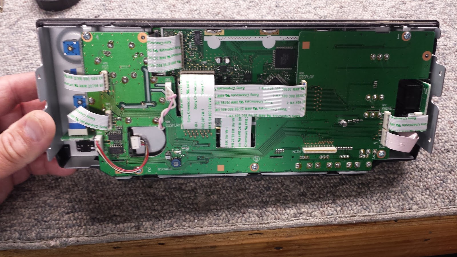
Back of the front panel...


Started disconnecting cables between the front panel and sub-logic boards...


Outer front panel (face of radio) removed...


Front panel with radio face removed...


PCB with back light inverter cover removed (upper RH side of board)...


The device in the lower RH side is the failed PNP transistor. It is soldered to a tiny pad of copper board, isn't even sinked to the rest of the copper. I remove that, remove the shield, drill a hole in the shield, attach a new device to the shield via thermal grease, and reinstall...


Here, you can see the device attached to the wall of the shield, with the shield re-installed. I use leads to extend the device back to the circuit board pads where the OEM part was soldered...


A view of the attaching screw for the new device, through the shield. The shield makes quite a nice heat sink for the small amount of heat generated.


A view inside of the inverter compartment, exposing the new output device. 


Power up testing on the new CCFL back light regulator. I set the internal range for very little adjustment, with the lamp at about 50% output.


Back in the shack of my friend and local ham. Looks great!


Thursday, January 24, 2019

A3S Assembly Notes for a Friend

I recently sold one of my reconditioned Cushcraft A3S antennas to Keith K6POC and wanted to take a few pics to help him with assembly. I'm posting them in my blog because it's easier to put the notes together for him to access, and maybe it'll help one of y'all sometime while assembling a similar antenna. This antenna was originally bought back around 1975 by a good friend K4CMH (now SK). I got it from him in the early 90's and rebuilt it for my own tower. I have now installed a Force 12 6el HF yagi, so I rebuilt it with new SS hardware, a few dimensional changes, and updated it with my longer lasting heat shrink trap caps. 


The traps were all disassembled, cleaned, internal connections tightened, checked with the grid drip meter, and tagged.


Cushcraft uses 3 different types of traps in this antenna, they call them TA, TB, or TC for trap type. The old stickers they put on the traps when mfg were long gone, so i marked them and tagged them with new labels later...

I've rebuilt a number of Cushcraft A3 and A3S antennas over the years. (The "S" just means Stainless Steel hardware). Cushcraft marks them with invisible ink (just kidding), so you're on your own if you mix the traps up on an older antenna. Turns out it's not too tough to figure out. Also, those crazy little plastic caps that go on the ends of the traps don't hold up very well, and I've found that 2" heat shrink seems to last a lot longer (and is cheaper to boot!).

I've uploaded a few bits and tips to my site that might help, in case you find yourself trying to identify the traps or rebuild one of these. One is a .pdf from Dale KG5U, one is a .txt file with my tips, and a .jpg pic of a trap with the heat shrink end caps. Hope that helps some of you!!

Go to my website at http://www.WB4IUY.net , mouse over [Workshop]. and select "Schematics Manuals". Scroll down to the Cushcraft section and you'll find it. 


I wound two different types of coils for coupling to the traps..one style for inserting into the trap, another type for slipping over the trap stub...


This is the guy I get this heat shrink from... good stuff, VERY UV resistant. 


The pic of one end of a trap with the new heat shrink cap on. NOTE** the end of the trap that has a screw that connects the outer shell of the trap to the stub ALWAYS goes towards the boom....


I cleaned all this old oxidation from the original steel clamps off the metal while reconditioning it. I use a wire brush and small belt sander. 


Traps and couplers ready for assembly...


The center spreader of the director and reflector assembly is mild steel, so I remove all rust and oxidation and cold galvanize it. The last one I did still looked good after 25 years in the sky!


Fresh cold galvanizing in place...


Take note, the director, driven and reflector center sections are grouped together. I marked the slide-in sections with black tape for ease of assembly. Just slip them in to the tape, and tighten the clamps. Lengths are correct. 


Director assembly bundled together...


Reflector assembly bundled together... 


New driven element composite center  insulator. I like this better than the fiberglass version that gets all frayed out in the sun...


The boom is separated on one side from the center coupler for shipment. Slip it back together to the black tape and tighten the clamp. 


Boom disassembled for shipment...


I marked the boom where the director, driven, and reflector assemblies should reattach.  This is the reflector point..


Driven element attaches here...


Director attaches here...


All traps are tagged per TA, TB, or TC version. 


Reflector traps assembled in the proper order and length...


Driven traps assembled in the proper order and length... 


I wrote DOWN on the bottom of the traps near the drain holes. Make sure those holes are always facing down when the antenna is assembled...


Director traps assembled in the proper order and length... 


Driven element..one side of coax connects here...


Driven element, other side of coax connects here...


Driven element all taged and ready for assembly. Slip the ends pieces in to the black tape bands and tighten the clamps. 


Big load of aluminum all finished and on the way to Ca. Enjoy it, Keith!


Tuesday, December 11, 2018

DXPeditions Page...

I can't say enough good stuff about NG3K's Announced DX Operations page on the web. It has really helped me keep up with DXPeditions and raise my country count. There's a link under most calls listed, that will automatically take you to DX spots for them, info on where to find more info, the approximate schedule dates, and loads of other info. If you're into DXing, be sure to bookmark it, and keep the page pulled up in the background...lots of info in one spot for DX hunting. I have it linked in the [DX Tools] section of my personal site, but you can get to it directly at https://www.ng3k.com/Misc/adxo.html . 


Dave WB4IUY


Monday, December 10, 2018

Cushcraft A3 Trap Tips...

I've rebuilt a number of Cushcraft A3 and A3S antennas over the years. (The "S" just means Stainless Steel hardware). Like a dummy, I once totally disassembled an antenna without marking the traps. Cushcraft marks them with invisible ink (just kidding), so you're on your own if you mix the traps up on an older antenna. Turns out it's not too tough to figure out. Also, those crazy little plastic caps that go on the ends of the traps don't hold up very well, and I've found that 2" heat shrink seems to last a lot longer (and is cheaper to boot!). 

I've uploaded a few bits and tips to my site that might help, in case you find yourself trying to identify the traps or rebuild one of these. One is a .pdf from Dale KG5U, one is a .txt file with my tips, and a .jpg pic of a trap with the heat shrink end caps. Hope that helps some of you!!

Go to my website at http://www.WB4IUY.net , mouse over [Workshop]. and select "Schematics Manuals". Scroll down to the Cushcraft section and you'll find it. 


Dave WB4IUY
http://www.WB4IUY.net


Saturday, December 8, 2018

Repairing a Tripp-Lite PR-40 DC Supply

TrippLite power supplies are well made, high quality supplies, but that negative lead regulation is a little odd and difficult to wrap your head around when it comes time to repair them. This supply to me inoperative, so I had to dig in deep to see what was wrong. 

First: TrippLite keeps the schematics for these close to their chest, so it took a bit of searching online to locate someone with an electrical schematic. FYI, there's a great site on yahoogroups for power supplies,  you should join it if you think you'll ever need a schematic or info on a power supply. The link to it is:

https://groups.yahoo.com/neo/groups/powersupplies/

I also uploaded a copy of the schematic in the [Schematics & Manuals] section of my website at:

http://www.WB4IUY.net


I discovered the remaining insulators on the output terminals had failed, and the rest were totally missing, shorting the output/crowbar board to the chassis. This took out all of the pass transistors and a few other bits. I replaced the pass transistors, fabricated new feed-thru insulators to protect the output studs from shorting to the case again, and rebuilt the crowbar circuit. Now, it'll go from no load to 40 amps @ 13.8 VDC with only 0.2 VDC shift. Solid supply! 

 Just cracking it open to take a look...

 Output / Crowbar board removed for inspection...

 Broken insulator...

 The only insulators left... There should be a feedthru insulator and a backup insulator in each stud...

 The PR-25, PR-40, and PR-60 use the same schematic... 2 pass transistors for the 25, 4 for the 40, and 6 for the 60.

 One pass transistor tacked in and boards jumped in place for testing...

 New insulators fabricated...the outside insulator is T-shaped and passes through the chassis, the inner parts are counter bored so they fit together. 

 Outside view with the new insulators in place...

All finished and ready to rock!!


Dave WB4IUY
http://www.WB4IUY.net